
Read Entire Manual Before Beginning Installation
Note: These instructions are for installation of the SmartStock Tuner Kit. If you don’t have an overhead mill or router and drill press do not attempt to install the SmartStock System in your rifle stock. Take it along with these instructions to a qualified gunsmith or machine shop or send your stock to us for installation.
Equipment Needed For System Installation
1. Overhead Milling Machine.
2. 0.656” (21/32) flat bottom mill bit.
3. 0.500” flat bottom mill bit.
4. 0.188” (3/16) flat bottom mill bit.
5. 7/32 or 15/64 drill bit with stop depending on the hardness of the stock material. A Laminate stock would require the larger bit than would a Composite stock. Use your best judgment..
6. 3/16 drill bit.
7. Bubble level.
8. Hand held drill motor.
Step 1. Check stock to make sure the existing front sling swivel screw hole is centered in the stock channel. This is very important. If it is not, then find the center of the stock barrel channel and mark a center line on it. Remove the sling swivel screw. If the retaining nut is visible, remove it now following instructions in Step 6.
Step 2. Fasten the stock securely to the mill bed using one or two vises as necessary.
Step 3. Place a small bit in the mill and adjust the mill bed until the bit is centered on the swivel hole or center line of the stock channel. See Fig. 4. Adjust the vise position so the stock is straight with the bed and not running off at an angle
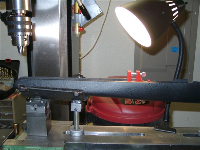
Step 4. Place a small bubble level on the flat front action area of the stock (not on the stock upper surface) and level it front to rear. See Fig. 1
Step 5. Place a bubble level across the top of the stock forend and level it to make sure it is not twisted or canted. See Fig. 2.
Step 6. Remove the old sling swivel retaining nut. If it is visible in the barrel channel then you can usually put a long 10/32 screw into it and either pry it up out of the stock using pliers or tap it out from the bottom. If it is imbedded in the stock and not visible on the surface, you will need to use your 0.656” mill bit to carefully mill down into the barrel channel until it is exposed. Then remove the nut as outlined above. Do Not attempt to mill out the stock barrel channel without first removing the retaining nut, if you do you will likely ruin the stock when the nut rips out as the bit runs into it
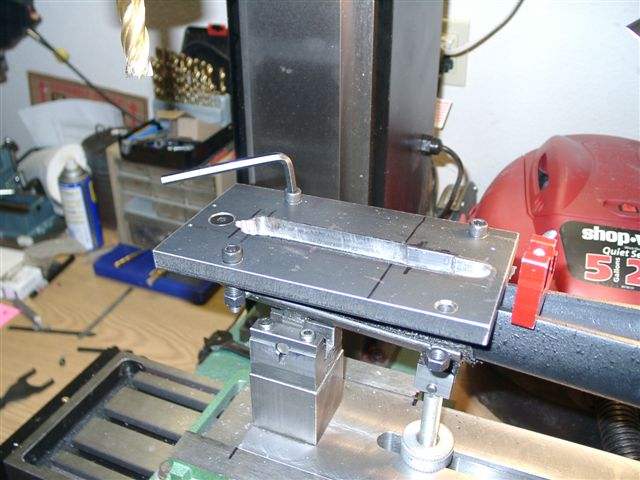
Step 7. Install the 0.656” mill bit into the machine. Move the table until the forward end of the bit is back 0.750” from the front end of the stock. See Fig. 3.
Step 8. Carefully lower the bit until it contacts the sides of the stock channel. Turn on the mill and slowly mill the stock barrel channel until the cut is just flush with the bottom surface of the barrel channel. See Fig. 5.
Step 9. Using this as a “0” depth, turn off machine and set your dial to “0”. Turn on machine and continue milling down into the barrel channel to a depth of 0.410”.
Step 10. Turn off your machine and lock your mill head at this depth.
Step 11. Using a dial caliper, measure the “Exact” length of the tuner unit.
Step 12. Mill out the stock barrel channel along the center line until you are approximately 0.05” or so less than the measured length. Do not exceed the length of the unit when milling or you will have to fill in the cavity with epoxy and re-do it. The unit when installed must not be able to be moved forward or backward.
Step 13. Check the milled area using the unit as a guide, and continue to mill very carefully until the unit has a snug fit in the cavity.
Step 14. Install the 0.500” mill bit into your mill. Lower it until it is just touching the bottom of the milled area. Mill the rear of the cavity an additional 0.375” to make room for the screw and nut that protrudes from the rear of the tuner.
Step 15. Move mill bed and center it on sling swivel hole. Set bit on bottom of channel. Mill down approximately 0.015” making a recess for the sling swivel screw retaining nut, it cannot protrude above the barrel channel surface.
Step 16. Install a 3/16 mill bit into your mill. Move the mill bed until the bit is just contacting the forward end of the milled out area. Lower the bit to the bottom of the cavity and set your dial to “0” depth.
Step 17. Raise the bit up off of the bottom 0.010” and lock your mill head.
Step 18. Mill a slot 0.500” or so toward the front of the stock. Be careful to leave at least 0.250” of material at the front end of the stock barrel channel.
Step 19. Remove the collet from the mill and install your drill chuck into it.
Step 20. Install a 7/32 or 15/64" drill bit into the chuck. Set stop to a depth of 0.320” from bottom surface.
Step 21. Drill a hole in the bottom surface of the barrel channel approximately 0.250” back from the front edge of the unit milled out area. Replace the 7/32 or 15.64” drill bit with a 3/16” drill bit and drill a smaller hole completely through the bottom of the stock.
Step 22. Re-install the 7/32 or 15/64" drill bit with stop and drill another hole approximately 0.250” forward of the rear end of the main unit inlet area. Replace the 7/32 or 15/64" bit with the 3/16” bit and drill a smaller hole completely through the bottom of the stock.
Step 23. Recheck that the unit fits into the inletted area and can be pushed all the way to the bottom of the milled area with your fingers.
Step 24. Remove the unit from the stock and remove the stock from the machine.
Step 25. Place a 3/16 bit into your hand held drill. Drill a hole centered in the front forend of the stock approximately 0.175” below the barrel channel, through into the inletted area. Be careful to make sure the hole is going straight and level, as it has to line up with the tuner adjustment screw.
Step 26. Screw a 2” long 8/32 round head screw into the top of one of the supplied barrel pressure adjustment allen screw inserts.
Step 27. Place stock forend on a flat surface while holding the butt between your legs and place the insert into the front hole. Tap the insert into place with a hammer until it is flush or just below the inletted bottom surface. Remove the screw.
Step 28. Repeat the above procedure for the rear adjustment screw hole.
Step 29. Place the sling swivel retaining nut into the stock and install a proper length sling swivel screw into it. With the screw installed make sure that it does not protrude past the top surface of the retaining nut. If it does, remove it and use a shorter sling swivel screw or cut it to the proper length.
Step 30. Install the two self locking allen set screws into the front and rear inserts from the bottom of the stock. Screw them in until the screw head is just level or below the top surface of the insert.
Step 31. Check to make sure that none of the screws are touching the bottom of the unit when it is installed. See Fig. 6.
Step 32. Insert the screwdriver into the hole in the front of the stock and make forward and backward adjustments to the unit. If you are unable to easily access the adjustment screw head you may have to elongate the hole slightly to allow the screw driver to index the adjustment screw properly.
The installation is now complete.
Fig. 1 Fig. 2 Fig. 3
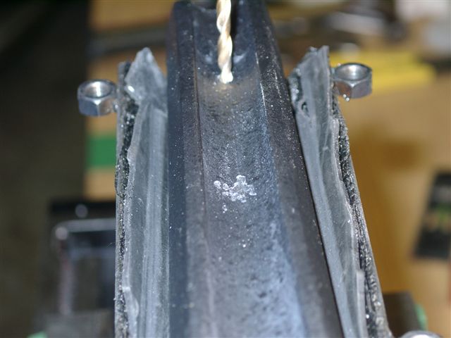
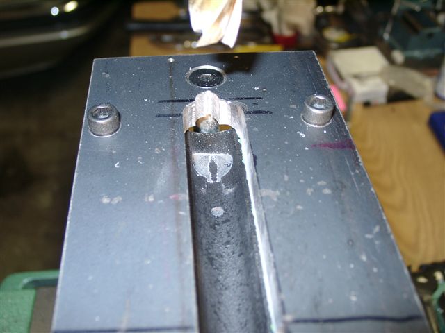
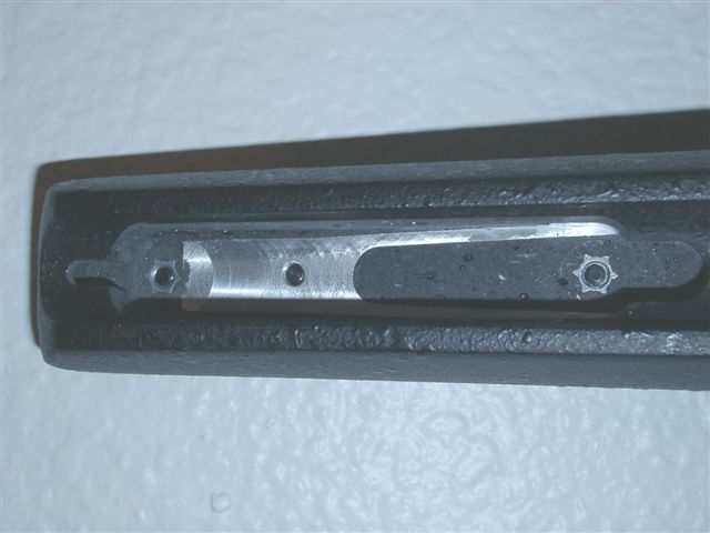
Fig. 4 Fig. 5 Fig. 6

Tuner Kit